ESP8266をWeb Serverとして使用します。同じローカルネットワークに繋がっている他のパソコンなどからhttpでアクセスできるようにします。
準備
パソコン、ESP8266
サンプルプログラムについて
ESP8266ボードをArduino IDEに追加すると、Arduino IDEからサンプルプログラムを使用することができます。サンプルプログラムは、「ファイル」→「スケッチ例」を選択すると、下の方に、「NodeMCU1.0 (ESP-12E Module)用のスケッチ例」の項目がありますので、そこから選択します。
今回は、「ESP8266WebServer」の中にある、「HelloServer」を用います。
8行目、9行目に使用するアクセスポイントのSSIDとパスワードを記入します。
#include <ESP8266WiFi.h>
#include <WiFiClient.h>
#include <ESP8266WebServer.h>
#include <ESP8266mDNS.h>

#ifndef STASSID
#define STASSID "your-ssid"
#define STAPSK  "your-password"
#endif

const char* ssid = STASSID;
const char* password = STAPSK;

ESP8266WebServer server(80);

const int led = 13;

void handleRoot() {
  digitalWrite(led, 1);
  server.send(200, "text/plain", "hello from esp8266!");
  digitalWrite(led, 0);
}

void handleNotFound() {
  digitalWrite(led, 1);
  String message = "File Not Found\n\n";
  message += "URI: ";
  message += server.uri();
  message += "\nMethod: ";
  message += (server.method() == HTTP_GET) ? "GET" : "POST";
  message += "\nArguments: ";
  message += server.args();
  message += "\n";
  for (uint8_t i = 0; i < server.args(); i++) {
    message += " " + server.argName(i) + ": " + server.arg(i) + "\n";
  }
  server.send(404, "text/plain", message);
  digitalWrite(led, 0);
}

void setup(void) {
  pinMode(led, OUTPUT);
  digitalWrite(led, 0);
  Serial.begin(115200);
  WiFi.mode(WIFI_STA);
  WiFi.begin(ssid, password);
  Serial.println("");

  // Wait for connection
  while (WiFi.status() != WL_CONNECTED) {
    delay(500);
    Serial.print(".");
  }
  Serial.println("");
  Serial.print("Connected to ");
  Serial.println(ssid);
  Serial.print("IP address: ");
  Serial.println(WiFi.localIP());

  if (MDNS.begin("esp8266")) {
    Serial.println("MDNS responder started");
  }

  server.on("/", handleRoot);

  server.on("/inline", []() {
    server.send(200, "text/plain", "this works as well");
  });

  server.on("/gif", []() {
    static const uint8_t gif[] PROGMEM = {
      0x47, 0x49, 0x46, 0x38, 0x37, 0x61, 0x10, 0x00, 0x10, 0x00, 0x80, 0x01,
      0x00, 0x00, 0x00, 0x00, 0xff, 0xff, 0xff, 0x2c, 0x00, 0x00, 0x00, 0x00,
      0x10, 0x00, 0x10, 0x00, 0x00, 0x02, 0x19, 0x8c, 0x8f, 0xa9, 0xcb, 0x9d,
      0x00, 0x5f, 0x74, 0xb4, 0x56, 0xb0, 0xb0, 0xd2, 0xf2, 0x35, 0x1e, 0x4c,
      0x0c, 0x24, 0x5a, 0xe6, 0x89, 0xa6, 0x4d, 0x01, 0x00, 0x3b
    };
    char gif_colored[sizeof(gif)];
    memcpy_P(gif_colored, gif, sizeof(gif));
    // Set the background to a random set of colors
    gif_colored[16] = millis() % 256;
    gif_colored[17] = millis() % 256;
    gif_colored[18] = millis() % 256;
    server.send(200, "image/gif", gif_colored, sizeof(gif_colored));
  });

  server.onNotFound(handleNotFound);

  server.begin();
  Serial.println("HTTP server started");
}

void loop(void) {
  server.handleClient();
  MDNS.update();
}
動作確認
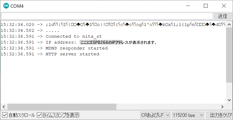
プロググラムをESP8266への書き込みが完了したら、シリアルモニタを開いて動作を確認しましょう(図1)。シリアルモニタには、ESP8266のローカルIPアドレスが表示されます。同じアクセスポイントに接続しているパソコン等のブラウザのアドレスバーに「http://(ESP8266のローカルIPアドレス)」を打ち込んで、ESP8266内部で動作しているWebServerにアクセスしましょう。
ブラウザに、「hello from esp8266!」と表示されるはずです。これは、上記プログラムの「handleRoot()」関数が呼び出されたことを意味します。同様に、「http://(ESP8266のローカルIPアドレス)/inline」、「http://(ESP8266のローカルIPアドレス)/gif」にアクセスし、確認しましょう。
次に、プログラムに対応させ、ESP8266の3Vピン–LEDアノード–LEDカソード–330Ω抵抗–GPIO13ピン(D7)となるように、LEDをつなぎましょう。サーバが起動している最中は、LEDが点灯します。
上記プログラムを改良して、「http://(ESP8266のローカルIPアドレス)/on」にアクセスするとLEDが点灯し、「http://(ESP8266のローカルIPアドレス)/off」にアクセスするとLEDが消灯するようにしてみましょう。
